In the field of engineering, mastering sheet metal bending stiffness in engineering plays a crucial role in enhancing the structural integrity and performance of various projects. By understanding the concept of flexibility and mastering its application, engineers can create designs that are not only aesthetically pleasing but also highly functional. In this article, we will explore the importance of orientation, the impact of increased “H” on structural stability, and the incorporation of bending stiffness for optimal project performance. So, let’s dive right in!
Table of Contents
Mastering Flexibility in Engineering
When we talk about flexibility in engineering, we are referring to the concept of flexural rigidity. Flexural rigidity is the measure of a material’s resistance to bending. It is calculated by multiplying the material’s moment of inertia by its Young’s modulus, giving engineers an insight into how readily the material can be bent without deforming permanently.
Flexibility is crucial in structural design as it allows engineers to create structures that can withstand various loads and deformations. By masterfully utilizing flexibility, engineers can find innovative solutions to design challenges, ensuring the longevity and versatility of their projects.
Understanding the Concept of Flexural Rigidity
Flexural rigidity is determined by two factors: the moment of inertia and the Young’s modulus. The moment of inertia measures the distribution of material around an axis, while the Young’s modulus represents the material’s stiffness or elasticity.
For example, materials with a larger moment of inertia and a higher Young’s modulus are less likely to bend and more resistant to deformation. This knowledge allows engineers to carefully choose materials and adjust their properties to achieve the desired level of flexibility for each specific project.
Practical Applications of Flexibility in Structural Design
The practical applications of flexibility in structural design are vast and diverse. Let’s take a look at a few notable examples:
- Architectural Design: Incorporating flexibility into architectural designs allows for the creation of iconic structures such as curved skyscrapers or suspended bridges. These structures not only captivate the eye but also demonstrate the power of engineering innovation.
- Aerospace Engineering: Flexibility plays a crucial role in aerospace engineering. Aircraft wings, for instance, are designed with a specific level of flexibility to withstand aerodynamic forces and environmental conditions, ensuring a safe and comfortable flight.
- Automotive Industry: In the automotive industry, flexibility is essential for designing cars that provide a smooth and stable ride. By carefully considering the flexibility of different components, engineers can optimize vehicle performance and safety.
These examples illustrate the wide-ranging impact of flexibility in structural design, emphasizing the importance of mastering sheet metal bending stiffness in various engineering fields.
Moreover, flexibility is not only limited to the field of structural design. It also plays a significant role in other engineering disciplines. For instance, in the field of robotics, engineers utilize flexible materials and joints to create robots that can adapt to various environments and perform complex tasks with precision.
Furthermore, flexibility is a key consideration in the design of medical devices. Medical implants, such as artificial joints or stents, need to be flexible to accommodate the natural movements of the human body while providing support and functionality. By carefully selecting materials with the right level of flexibility, engineers can ensure the success and longevity of these life-changing medical devices.Orientation in engineering is a fundamental concept that plays a vital role in the design and construction of various structures. It goes beyond just the physical positioning of materials; it involves a deep understanding of how the orientation of components can affect the overall functionality and durability of a project.In civil engineering, for example, the orientation of steel reinforcements in concrete structures is carefully planned to ensure optimal load-bearing capacity and resistance to external forces. By strategically aligning these reinforcements, engineers can enhance the structural integrity of buildings, bridges, and other infrastructure.Furthermore, in mechanical engineering, the orientation of components in machinery can determine its efficiency and longevity. By aligning gears, shafts, and other moving parts correctly, engineers can minimize friction, reduce wear and tear, and improve the overall performance of the machine. This attention to orientation is crucial in industries where precision and reliability are paramount, such as aerospace and automotive engineering.
Enhancing Structural Stability with Increased “H”
In engineering, “H” represents the height of a shape or section. Increasing the “H” of a material, such as a beam or column, can have a profound effect on its structural stability and load-bearing capacity.
Calculating Area Moment of Inertia for Different Shapes
Before delving into the impact of increased “H,” it’s important to understand how to calculate the area moment of inertia for different shapes. The area moment of inertia measures a shape’s resistance to bending. Let’s consider a few common shapes and their respective formulas:
- Rectangular Beam: The area moment of inertia for a rectangular beam is (b * h^3) / 12, where “b” represents the width and “h” represents the height.
- Circular Tube: The area moment of inertia for a circular tube is (π * (Ro^4 – Ri^4)) / 4, where “Ro” is the outer radius and “Ri” is the inner radius.
- I-Beam: The area moment of inertia for an I-beam can be calculated as a sum of the individual rectangular components.
By accurately calculating the area moment of inertia, engineers can assess the bending stiffness of different shapes, ultimately aiding in the selection of suitable materials for specific engineering projects.
The Impact of Increased “H” on Structural Performance
Increasing the “H” of a shape, such as a beam or column, significantly enhances its structural performance. By increasing the height, engineers can distribute the load more effectively, reducing stress concentrations and improving overall stability.
The increased “H” also allows for greater cross-sectional area, resulting in increased resistance to bending moments and shear forces. This translates to improved load-bearing capacity, ensuring that the structure can withstand higher loads without failure.
Moreover, increasing the “H” of a material can also have a positive impact on its deflection characteristics. When a load is applied to a beam or column, it experiences deflection, which is the amount of bending or deformation that occurs. By increasing the “H,” engineers can reduce the deflection, making the structure more rigid and less prone to excessive movement or sagging.
Furthermore, the increased “H” can also improve the natural frequency of a structure. Natural frequency refers to the rate at which a structure naturally vibrates when subjected to external forces. By increasing the “H,” engineers can adjust the natural frequency to avoid resonance, a phenomenon where the structure vibrates excessively due to the frequency of the external forces matching its natural frequency. This ensures that the structure remains stable and avoids potential damage or failure.
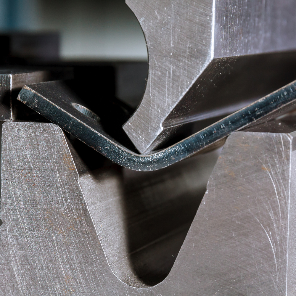
Exploring Bending Load Experiments in Engineering
To understand the implications of bending stiffness in real-world scenarios, engineers often conduct bending load experiments. These experiments involve subjecting different materials and shapes to controlled bending forces, allowing engineers to observe their response and determine their flexibility characteristics under various conditions.
Bending load experiments provide invaluable insights into the behavior of materials and assist engineers in making informed decisions when it comes to material selection, design optimization, and structural analysis.
During these experiments, engineers carefully measure and analyze parameters such as bending moment, stress distribution, and deformation patterns to gain a comprehensive understanding of how materials behave under bending loads. By studying these factors, engineers can predict potential failure points, optimize designs for maximum strength and durability, and ensure the safety and reliability of structures in real-world applications.
Furthermore, advancements in technology have enabled engineers to simulate bending load experiments using computer-aided design (CAD) software and finite element analysis (FEA) tools. These virtual experiments allow engineers to explore a wide range of scenarios, test different materials and geometries efficiently, and iterate on designs rapidly to achieve optimal performance and cost-effectiveness.
Incorporating Bending Stiffness for Optimal Project Performance
Now that we have explored the fundamentals of sheet metal bending stiffness, let’s delve into how engineers can effectively incorporate it into their projects for optimal performance.
How Bending Stiffness Affects Structural Integrity
Bending stiffness plays a crucial role in maintaining structural integrity. When a load is applied to a structure, it generates bending moments that cause the structure to deform. By incorporating appropriate bending stiffness, engineers can mitigate excessive deformations, prevent structural failure, and ensure the longevity of their projects.
Tips for Utilizing Bending Stiffness in Engineering Projects
Here are some tips for engineers looking to make the most of bending stiffness in their projects:
- Material Selection: Choose materials with suitable flexural rigidity for the specific project requirements.
- Orientation Optimization: Properly orient the materials to maximize their inherent properties and minimize weaknesses.
- Design Iterations: Conduct iterative design processes to optimize the bending stiffness based on performance simulations and detailed analyses.
- Realistic Load Testing: Perform thorough load testing to validate the bending stiffness and ensure the structure’s performance meets the desired standards.
By following these tips and considering the principles of bending stiffness, engineers can create projects that are not only visually striking but also structurally robust and reliable.
Conclusion
Mastering sheet metal bending stiffness in engineering is vital for creating structures that are both flexible and stable. By understanding the concept of flexibility, considering the importance of orientation, and incorporating bending stiffness, engineers can optimize the performance and longevity of their projects. Through careful material selection, thoughtful design iterations, and realistic load testing, engineers can create structures that stand the test of time while pushing the boundaries of innovation in the field of engineering.